ModbusTCP protocol
1. Simple Connector Page
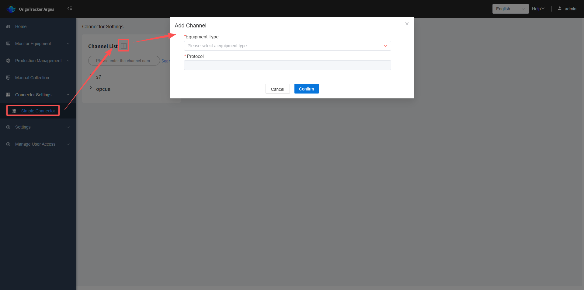
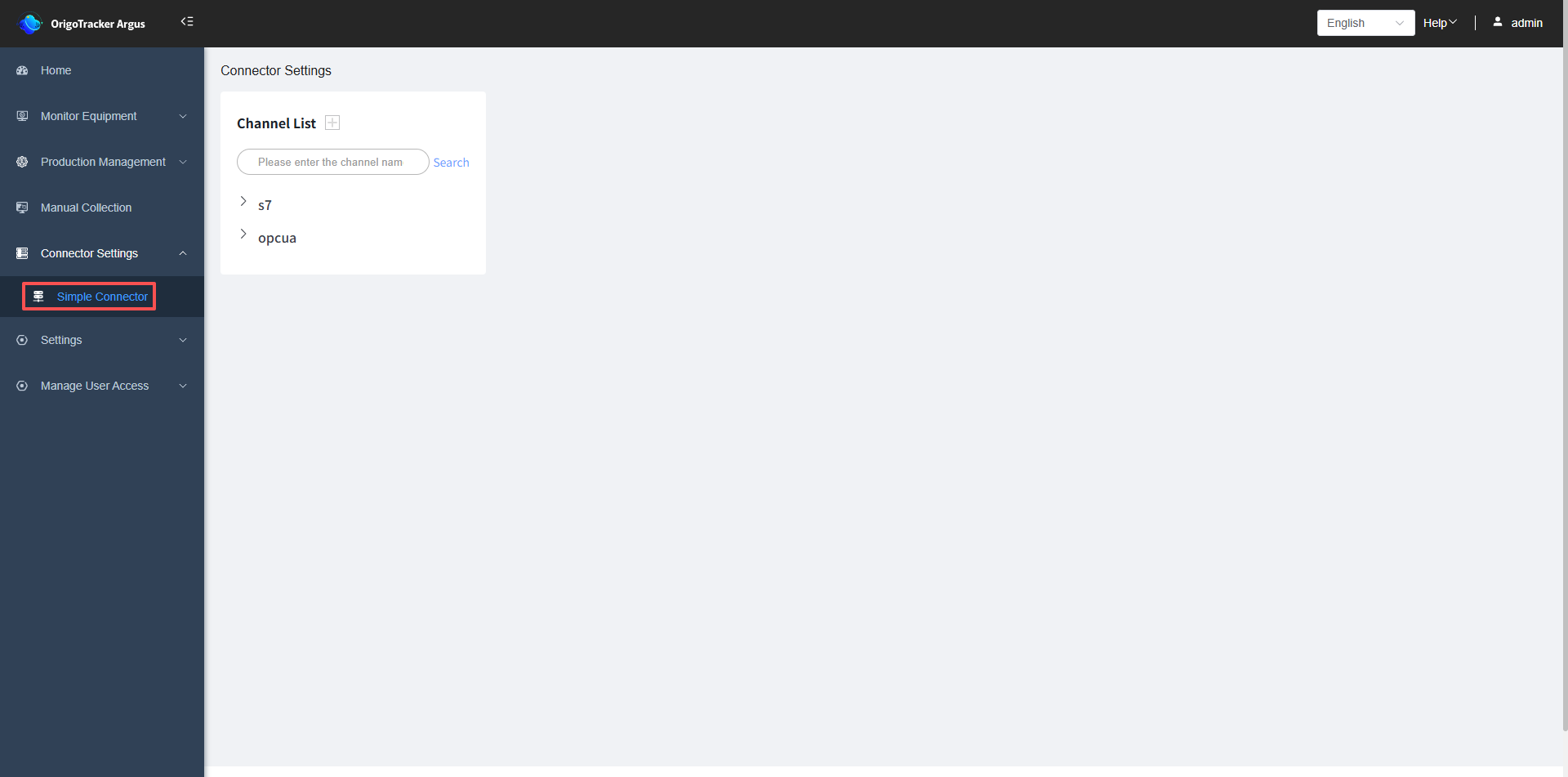 Click the plus sign next to the Channel List, add a ModbusTCP protocol.
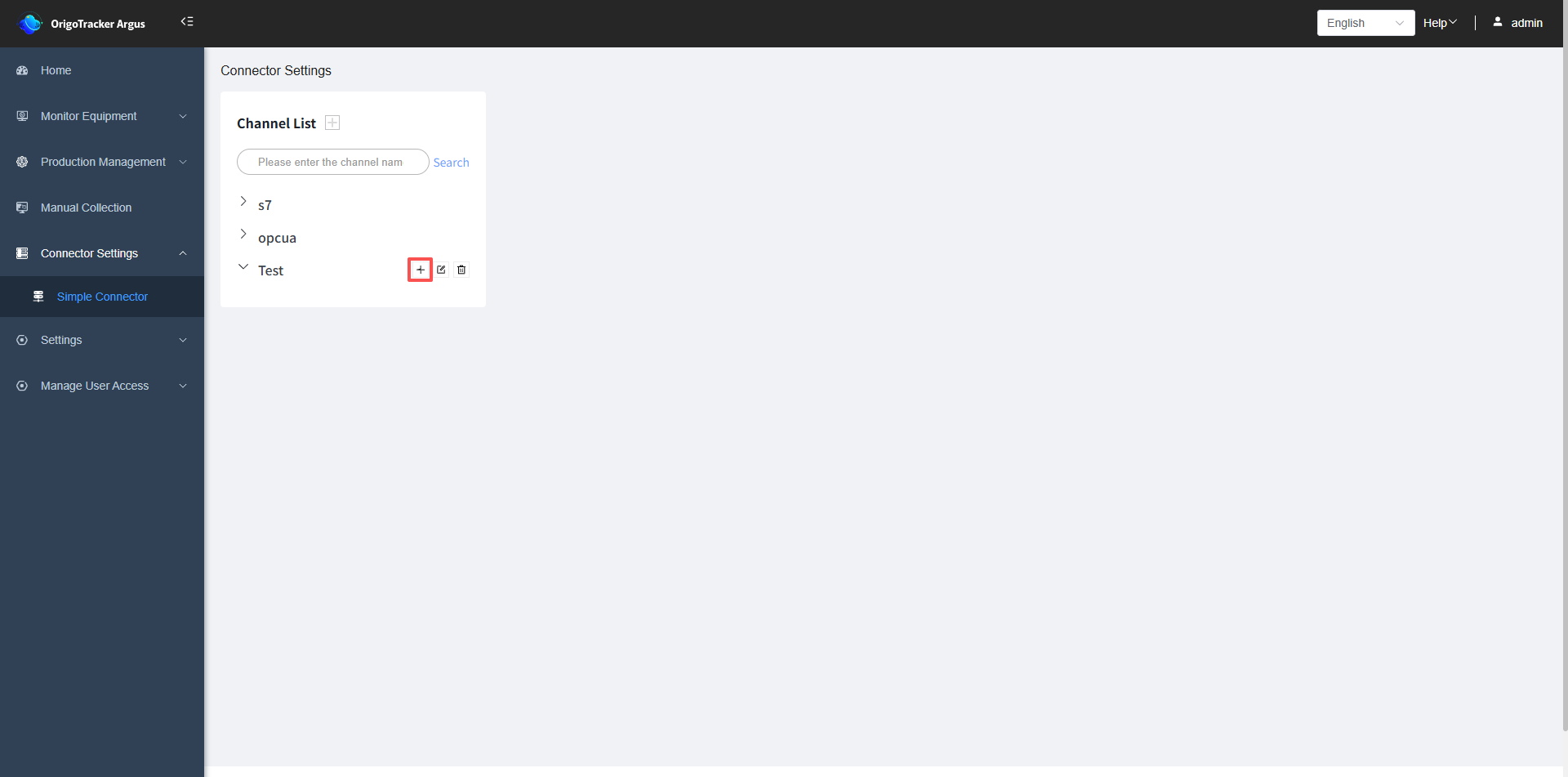
2. Add a PLC connection under the channel
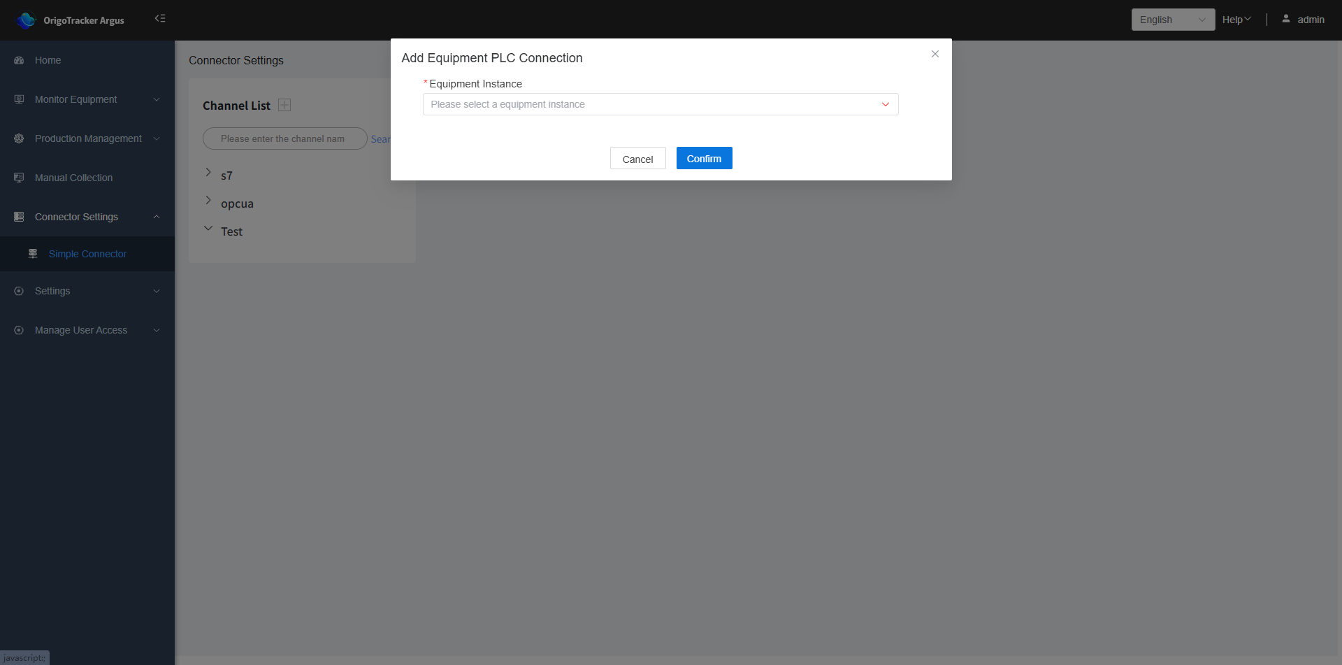
After adding the channel, click the plus sign to the right of the channel name to add a PLC connection under it.
| Field | Description |
|---|---|
| Equipment Instance | Select the equipment instance under this channel. If no equipment instance has been added, click here to see how to add one. |
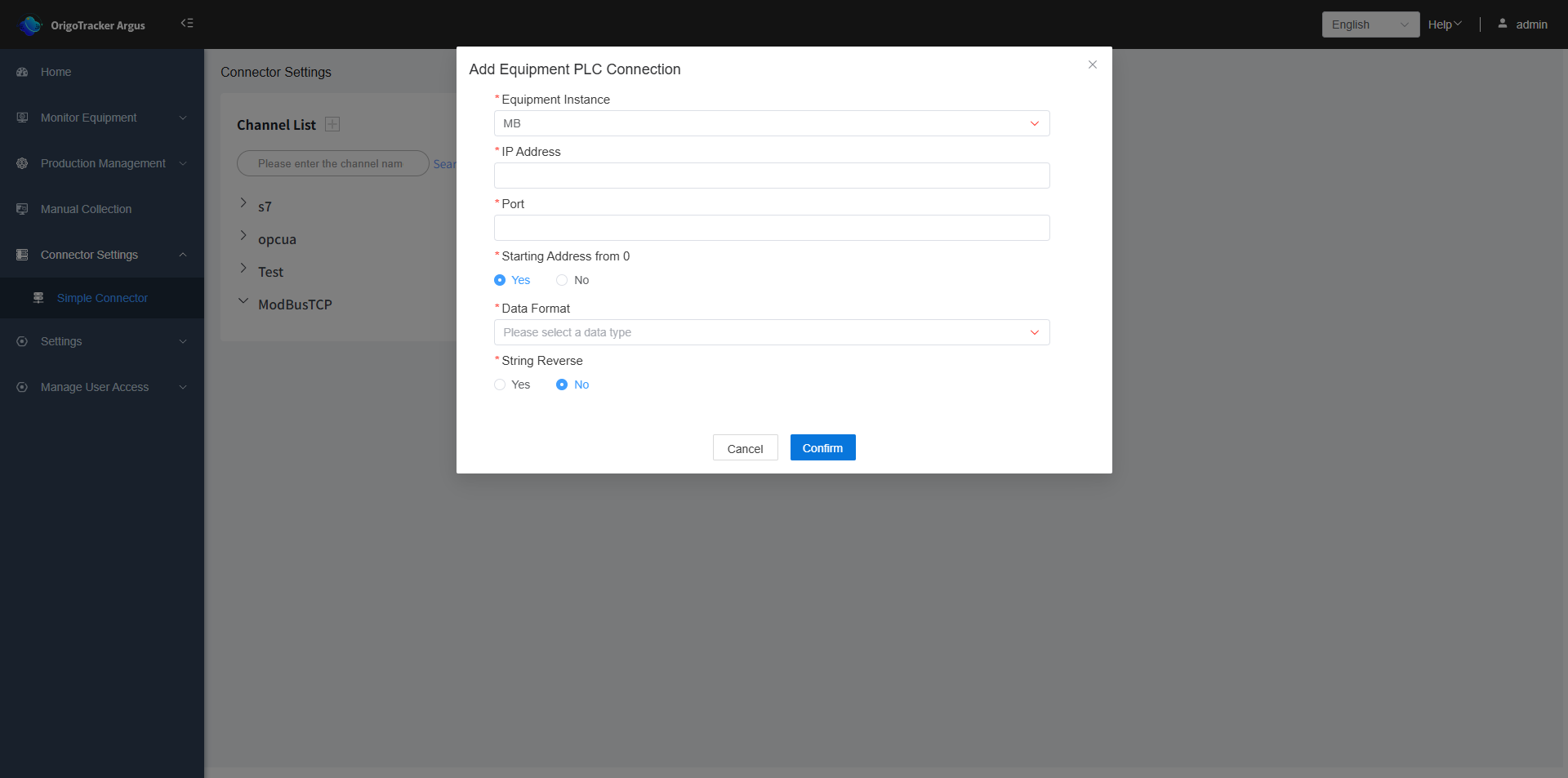
After selecting the instance, you need to fill in the relevant information.
| Field | Description |
|---|---|
| IP Address | The IP address of the PLC. |
| Port | The IP address port number of the PLC. |
| Starting Address from 0 | If the starting position of the data is 0. |
| Data Format | The data format for Modbus. |
| String Reverse | The arrangement of strings in Modbus. |
3. Add tags within the PLC device.
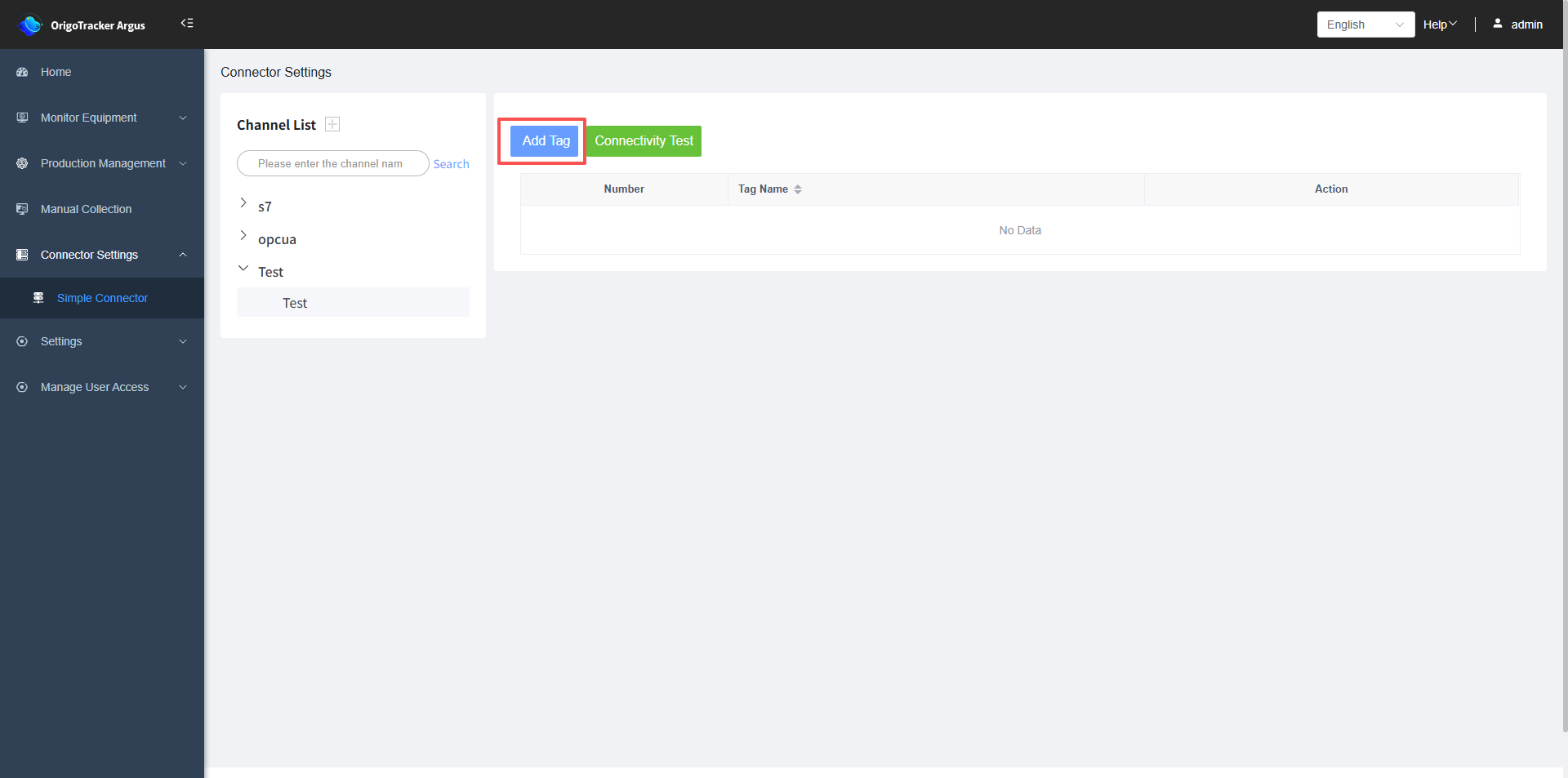
Select the PLC connection, and click "Add Tag" on the right.
| Field | Description |
|---|---|
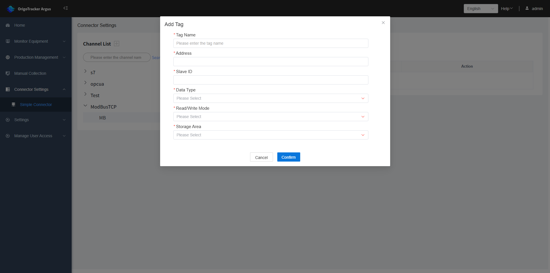
| Tag Name | The name of the tag. |
| Address | The address of the PLC data tag. |
| Station ID | The station ID required by ModbusTCP |
| Data Type | The data type of the PLC data tag. |
| Read/Write Mode | Select whether the PLC data tag is read-only or read-write. |
| Storage Area | the storage area of Modbus TCP |
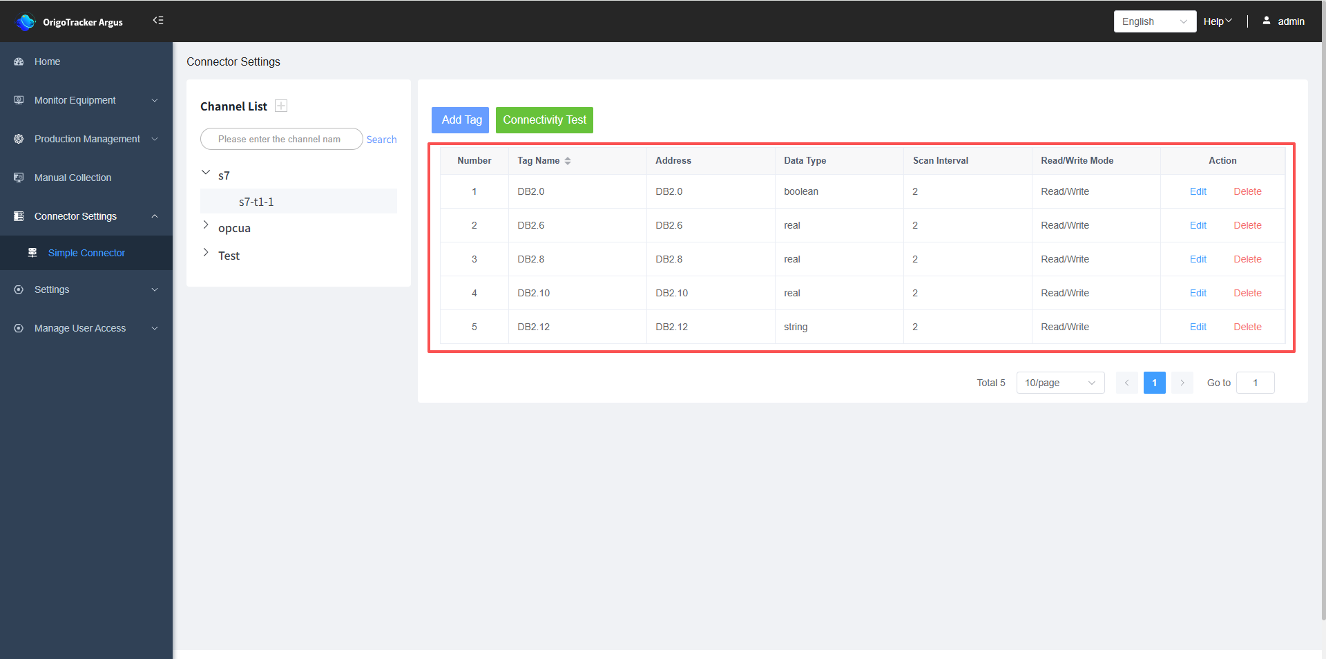
After completion, the tags you added will be displayed on the right side.
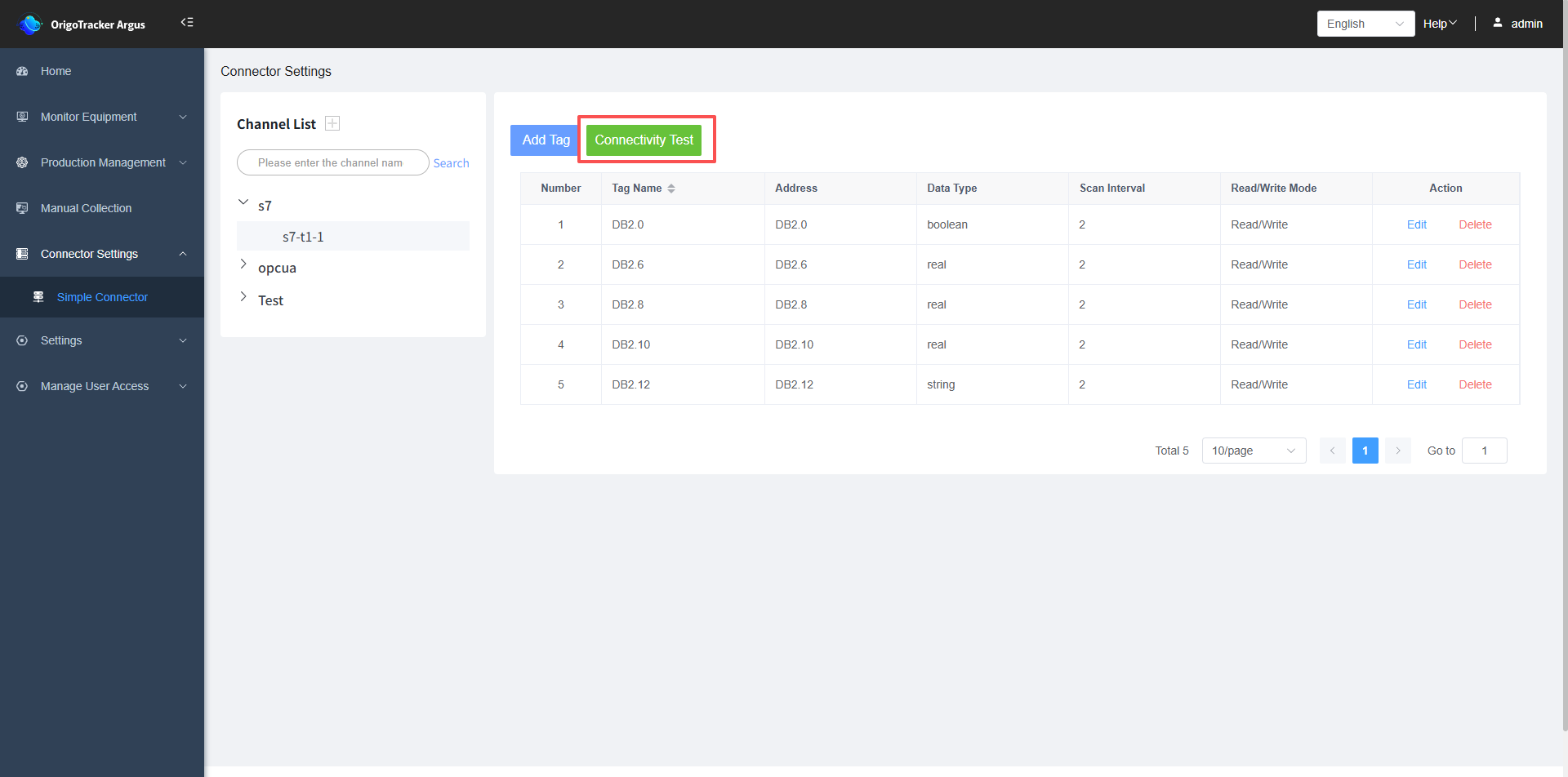
4. Connectivity Testing
After adding device tags, we can test the tags to see if they can connect to the PLC.
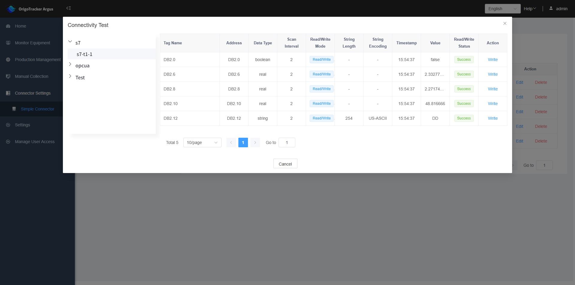
An access status of "Success" indicates that it can connect to the PLC, meaning the tag is functioning correctly.
If it shows "Failure", this means the PLC tag cannot be read, there is a connection issue. )
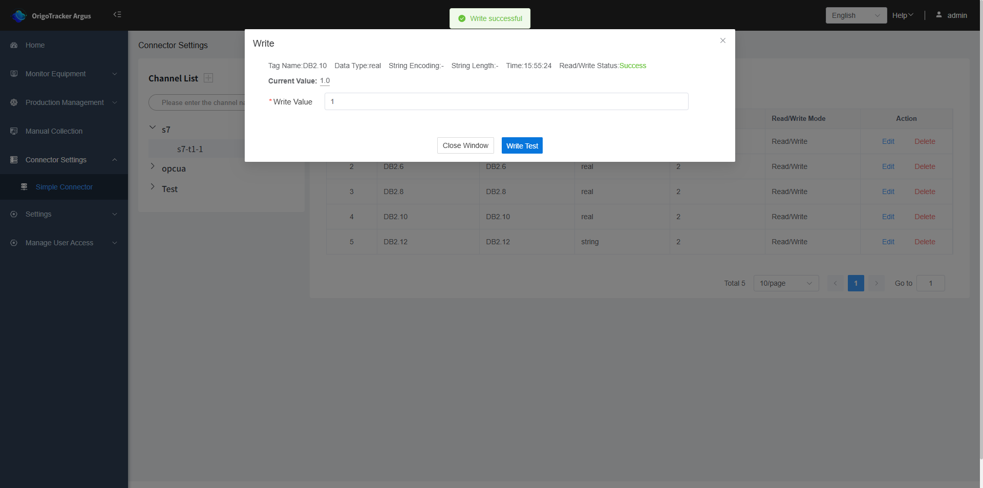
Click "Write" to perform a write test (only tags with a read/write mode set to "Read/Write" can be used for write testing).
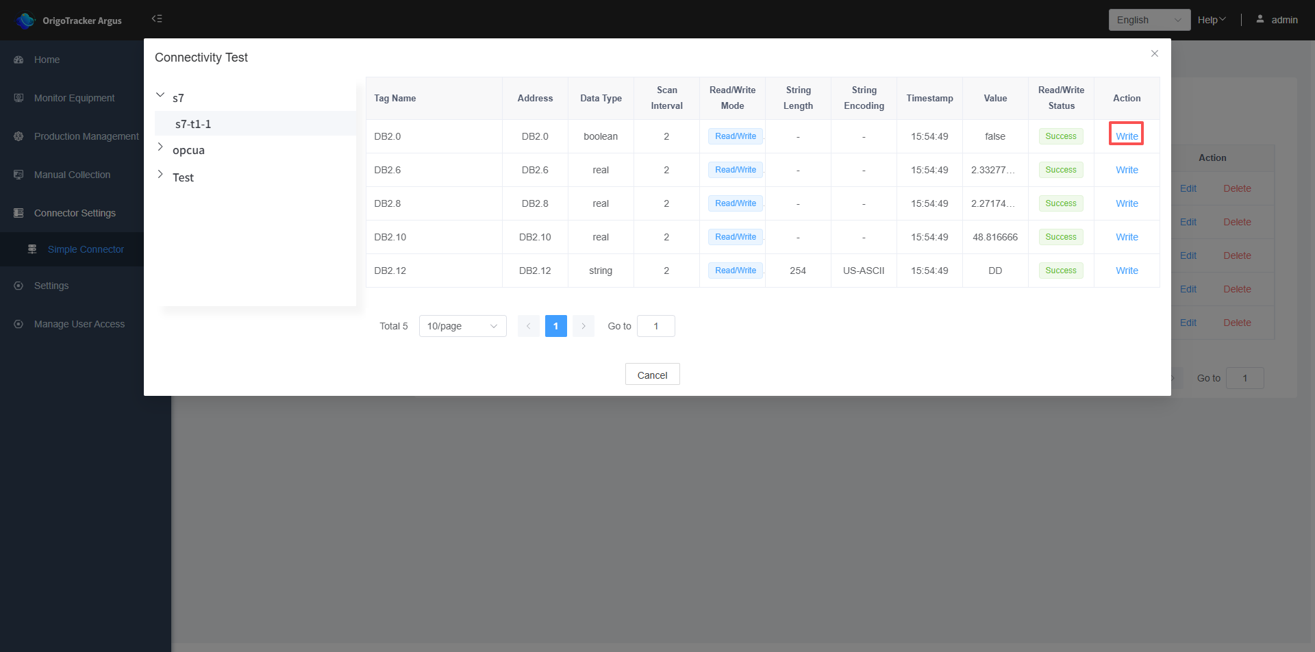
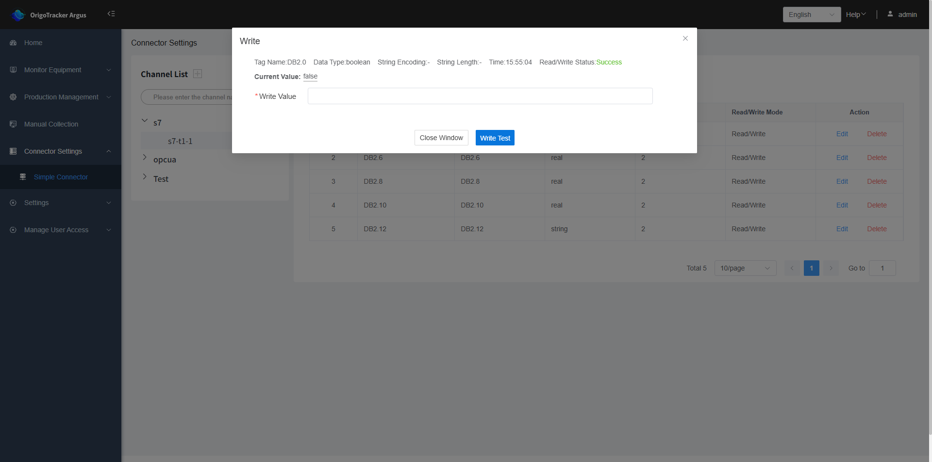
After filling in the data value and submitting, a "Write successful" message will be displayed upon successful writing.